Overdick
Optimised design
Design of large diameter monopile wind turbine foundation structures
Introduction
Decreasing subsidies and increasing competition in the offshore wind sector require cost and time efficient engineering approaches. The ability to combine several engineering disciplines and create an integrated design of wind turbine foundation and transition piece structures in every design stage is considered as a major benefit for project schedule, cost monitoring and quality  management.
Engineering requirements
Offshore wind turbine support and foundation structures require highest engineering standards with keeping the project costs on a low level at the same time. The design process combines different engineering disciplines such as structural, geotechnical, electrical, hydrodynamic, fabrication planning, transport and installation. With know-how and state-of-the-art engineering tools in all of these disciplines Overdick is working in interdisciplinary project teams to provide an integrated design and finding the best solutions from tender to detail design.
A sound understanding of all relevant parameters and their interaction is essential to efficiently optimise the entire system. Large diameter monopiles wind turbine foundations are of special interest since these structures have shown to be the most cost efficient foundation types for the majority of the currently planned wind farms located in medium water depth.
Large diameter monopiles
The foundation pile diameters are currently reaching up to 8.5 m. With these large diameters, the traditional design toolbox is reaching its limits. This requires a re-thinking of the applicable tools to create a safe and reliable, yet economical and efficient monopile design.
A variety of advanced and problem-dedicated design and calculation tools enable Overdick’s engineers to address challenges linked with hydrodynamic loads in extreme waves, cyclic loading effects, fatigue assessment, pile driving and pile handling.
The general design optimisation of large monopile foundations results in constantly changing geometry during the design cycle. For an efficient and reliable handling of monopile and location data Overdick uses a database system, ensuring all analysis models are generated according to the latest design stage. The design process is highly automated, ranging from database driven primary steel model generation, cluster study or site specific model set-ups up to post-processing.
Additionally, design details, such as flange connections and the loadings on the monopile appendices, have a significant influence on the overall performance of monopiles. Two selected design details with the chosen engineering approach using advanced simulation methods to establish an optimised design are presented within this article.
Pile driving assessment including flange design
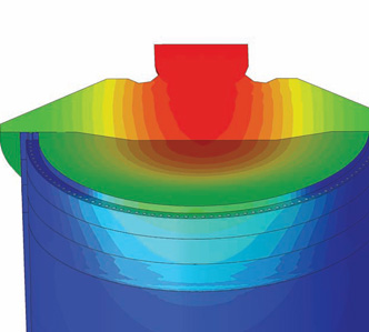
The combined function of a monopile flange as a support for the driving hammer and as a connection to the wind turbine tower for the entire life of the structure sets high demands on the analysis of the fatigue strength and verification. Both, the flange and the hammer anvil are built with tight but existing tolerances, which can impair the fatigue life significantly. Therefore, the fatigue life of  the flange has to be analysed with a nonlinear finite element (FE) approach by using advanced finite element simulations.
The tolerances are small compared to the overall dimension of the structure and therefore an accurate and rather fine FE mesh configuration needs to be used.
To account properly for the vertical pile displacement during the impact of the hammer anvil, the support condition of the pile in the soil needs to be reflected in a proper way. Using of nonlinear elastic-plastic material law derived from an accompanying driving analysis and included in the FEM simulation with springdamper elements is state of the art and leading to good results.
The fatigue damage of a single hammer stroke can be obtained by reading out the resulting stress history and performing a rainflow counting. Detailed fatigue damage assessments are finally conducted for the hot spot regions showing high peak stresses.
With certain experience, also two-dimensional approaches can be conducted in the early concept phase for determining appropriate flange designs at the beginning of a project.
Load Assessment on Monopile appendices
Due to maintenance and access requirements the monopiles are equipped with several appendages like boat landings or service platforms. Service platforms are usually located above the highest expected wave crest. However, very large waves approaching the monopile will run-up the pile and create comparatively high loads on the appendages. These loads may further become the governing criteria for the structural design of the appendages.
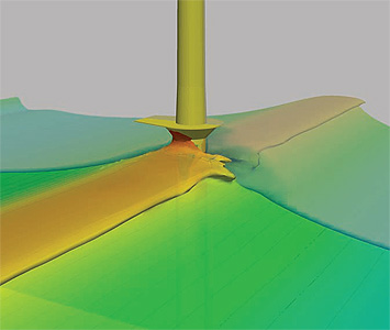
Usually these wave run-up loads are determined based on empiric formulations which, due to their approximate nature, yield rather high loads. As an alternative, loads on these structures can also be determined using first principle methods, in this case viscous 3D multiphase CFD simulations (see figures).
Due to the constantly-developing computational power and software tools, the effort for such a simulation today has become rather small and should be considered as standard load determination for deriving optimised design loads. Experience at Overdick has shown that by the use of such methods the resulting design can be significantly optimised.
Advanced engineering as key for optimisation and cost savings
Large diameter monopile design may require new approaches on engineering tools and verification methods. Advanced simulation technologies allow a direct load simulation and offer optimisation and associated cost saving potential for this new type of offshore foundation structures.
Overdick is capable of covering all relevant disciplines for the design of large monopile foundations, using the latest and advanced design methods in combination with more than 17 years of offshore structural design experience.
Overdick
Services: Offshore engineers and naval architects