Designing a high-performing filtration system – whatever the circumstances By Tim Nich
CLEAN delivery
Sometimes it makes sense to reuse existing gas turbine equipment and associated filtration system at another site – but it is important that a filtration solution is designed for the specific, real-world environment in which it is installed. So, how can you be sure of an efficient, reliable, and effective solution when the system moves to a new site?
From time to time, the change in energy markets can demand projects to be delayed or cancelled. This can come from government policy change or even a lack of resources available, such as natural gas. When asked to adapt an existing system to be used at a different location – this requires experience and deep understanding of all elements of the filter house and the unique site conditions, along with the flexibility to re-engineer a successful solution.
While reusing existing equipment offers significant cost savings, it also presents some difficult engineering challenges. One of the first issues to address when re-using a system is its footprint. While parts of the filter house may remain the same, a change to environmental conditions will likely require adjustments to be made to the filtration other equipment, such as water removal systems, may need to be installed.
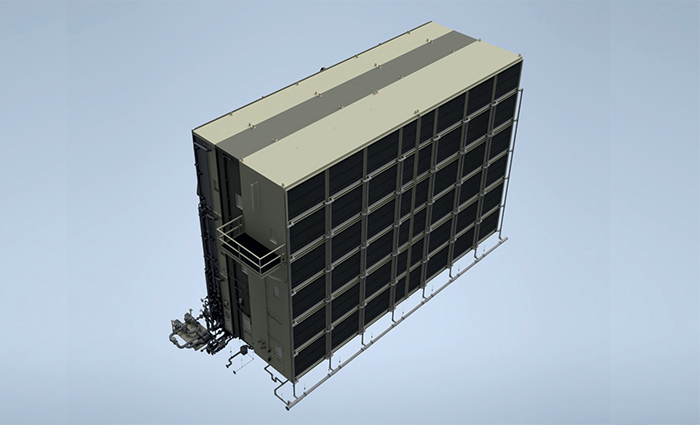
There is much to be considered in the design of the inlet filter house and this all needs to be engineered to fit into the existing footprint. The move from a dry dusty area, to one with higher moisture and rainfall will require new systems to handle water and humidity to prevent sudden system blockages. Is the installation near the sea? If so, it needs to be designed to handle salt, which is hygroscopic in nature and will quickly move between solid, sticky, and liquid states in the presence of moisture. Are different filtration stages required to deal with volumes of dust and sand? Will a pulse system be required to periodically clear filters in high dust regions, and has this been configured to ensure continued, reliable operation? Does access for maintenance require a change to walkways, and has the aerodynamics of the overall air inlet flow been designed and modelled to optimize GT performance?
 Why are aerodynamics so important? GTs consume huge volumes of air and, especially for smaller or highly compact GT packages, suboptimal aerodynamics can affect efficiency, power output, and overall reliability. A uniform airflow through the filter bank is essential to minimize the pressure loss, and to ensure the filter efficiency and filter life are optimized. The overall design of the filter house should encourage an even distribution of flow across the whole filter array. If the flow is not optimized, the operation of the filters and the GT itself will be compromised. Why is this? If a system has been designed to operate with 500 filters, for example, but an uneven air flow means only 400 are being fully utilized, these 400 filters are doing the work designed for 500. This can result in pressure loss, shorter filter life and, potentially, lower filter efficiency.
To ensure good aerodynamics throughout the GT inlet, requires consideration for layout and elevation. Sharp angles and transitions that are not smooth will affect air flow. Even prevailing winds and the location of external structures need to be considered: if the air inlet is positioned next to a wall, it is inevitably going to reduce air flow efficiency. If the filter house is installed low down, the filtration system may suck up dust from the ground. If it is situated near sources of emissions, this will attract additional particulates that will need to be handled by the system.
Whether a new filtration system or for the repurposing an existing one, while experienced filtration engineers may be able to assess risk areas, good Computational Fluid Dynamics (CFD) simulation is an essential tool for highlighting problem areas. It will help ensure all components of the filter house are interacting correctly and enable different solutions to be considered to optimize the system for both performance and cost. This can be especially vital in studying the options available in an existing footprint and give insight into how GTs and their inlet house will perform in their real-world conditions. The aim is to have no nasty surprises once the system is running!
Summary
The design of an inlet house for a GT installation requires in-depth understanding of the complex issues presented by different real-world environments and the interaction of different components required to ensure a maintainable, long-lasting, high performing solution.
There are occasions when it makes sense to repurpose an existing system and significant cost savings can be made. However, the engineering challenges to optimize the performance of such a solution should not be underestimated. It requires significant experience, a company that can work closely with site engineers, and deliver the flexibility and ingenuity to ensure reliable, predictable protection of the GTs. If the inlet filter house is designed correctly, operators can achieve optimum GT efficiency and extend system life and availability, while reducing overheads.
Tim Nicholas
www.parker.com/gtf
www.parker.com
parkerhannifin.com
Tim Nicholas is PowerGen Market Manager, Gas Turbine Filtration Division, Parker Hannifin. With more than 50 years of experience delivering innovative solutions for gas turbine inlet filtration and monitoring fleet-wide performance data, Parker’s Gas Turbine Filtration Division provides a full range of inlet systems and filters engineered to help customers meet their operating goals. Parker Hannifin is a Fortune 250 global leader in motion and control technologies.